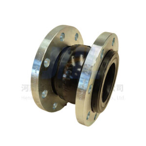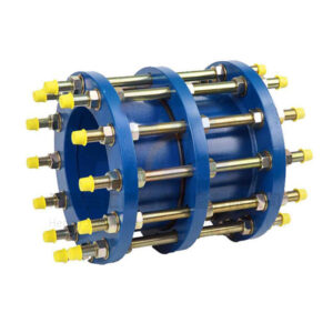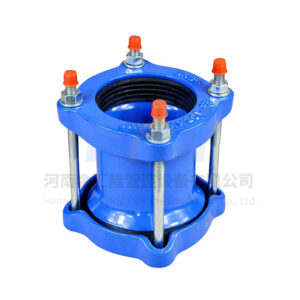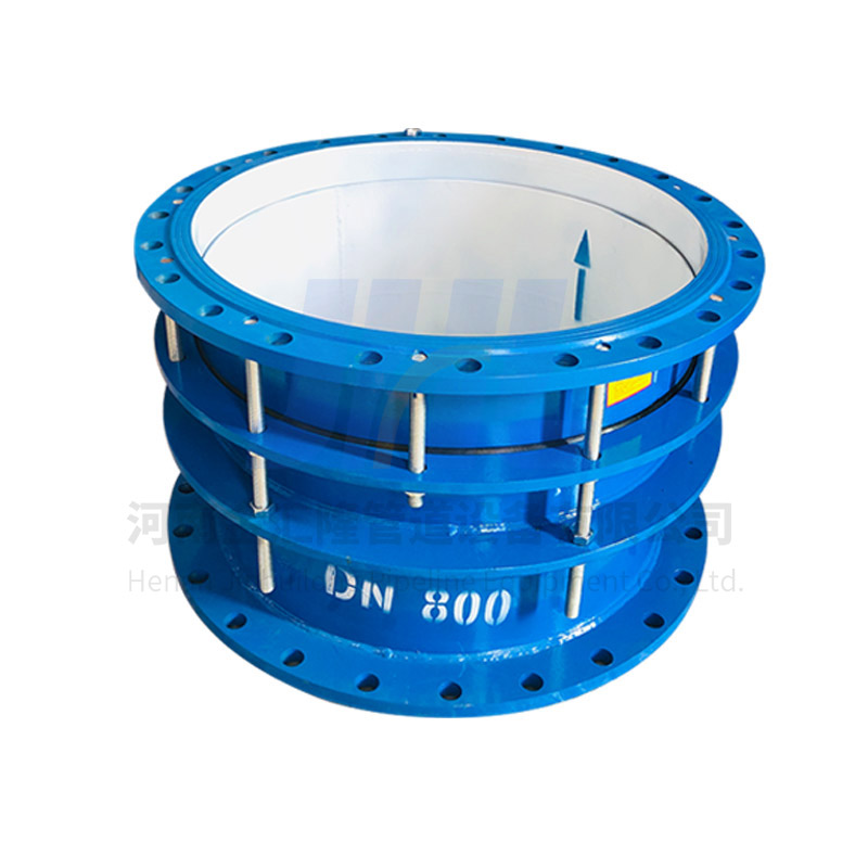
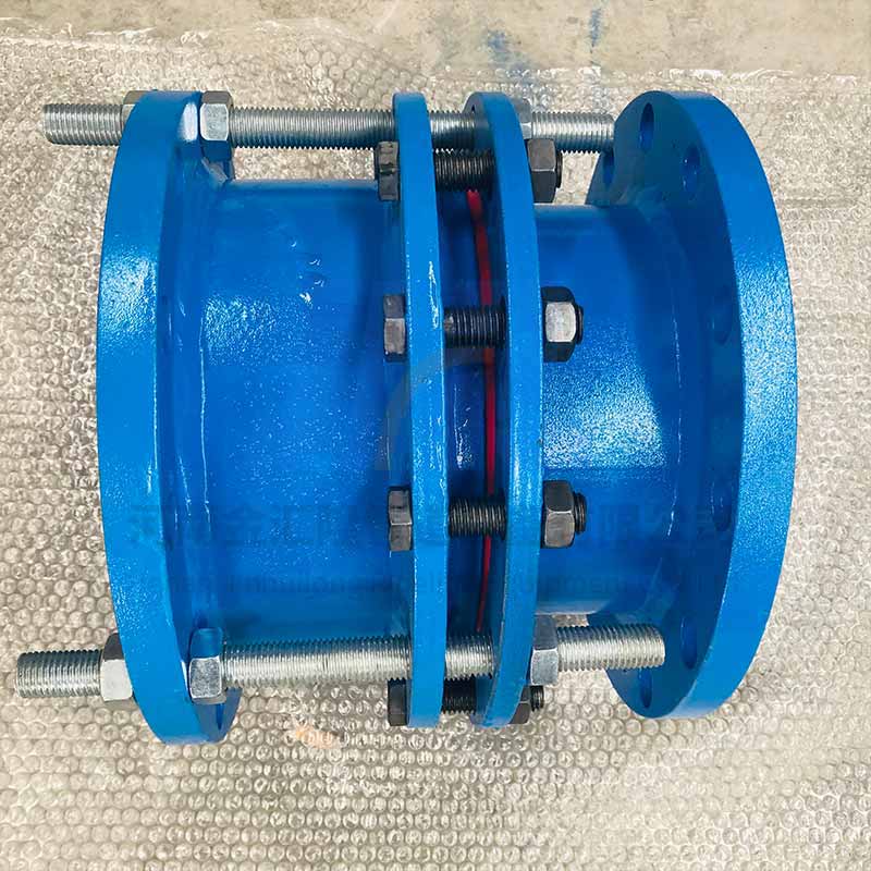
The double-flange limited expansion joint mainly consists of: the main body, sealing ring, gland, limiting screw, limiting expansion pipe, and nuts and bolts. Its function is to prevent excessive pipe displacement that could lead to leakage and damage of the expansion joint. It is primarily used to withstand the pressure and thrust of the pipeline within the allowable displacement range.
The double-flange limited expansion joint is based on the standard expansion joint but with the addition of a limiting screw device. The pipe can expand and contract freely within the specified range. However, if the expansion exceeds the maximum allowable limit, the double nuts on the limiting screw will fix the expansion amount, thus acting as a limit. This compensates for axial displacement, twisting, and eccentricity of the pipeline caused by thermal expansion and contraction or foundation settlement, thereby protecting the connected pump or valve.
Installation Method:
The double-flange limited expansion joint is suitable for connections where both ends are connected to flanges. During installation, adjust the connection length between both ends of the product and the flanges, and tighten the gland bolts diagonally and evenly. Then adjust the limit nuts. This allows the pipeline to expand and contract freely within the expansion range, locking the expansion amount and ensuring the operation of the pipeline. It is suitable for pipelines where both ends are connected to flanges. During installation, adjust the installation length between both ends of the product and the flanges, and tighten the gland bolts diagonally and evenly to form a single unit with a certain amount of displacement. This facilitates adjustment according to on-site dimensions during installation and maintenance. During operation, it can transmit axial thrust to the entire pipeline, reducing the pressure thrust (blind flange force) on the connected components and compensating for pipeline installation errors. Double-flange force transmission joints cannot absorb axial displacement. Double-flange force transmission joints are mainly used for loose connections of pumps, valves, and other accessories.
Material:
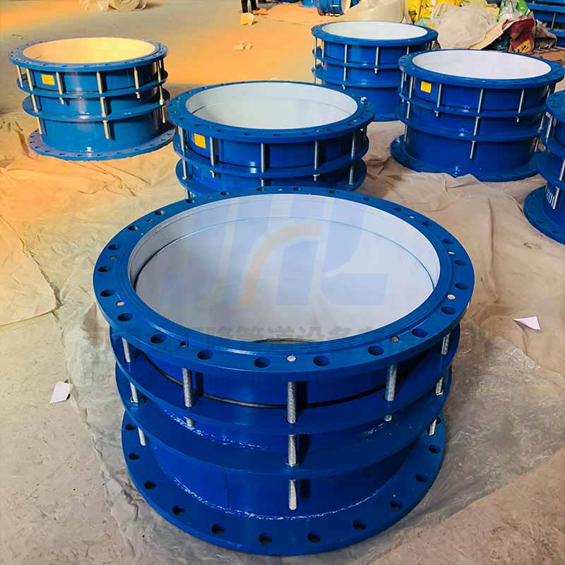
The materials for double-flanged expansion joints mainly include Q235 carbon steel, stainless steel, cast steel, and ductile iron. Different materials and models are selected for different applications.
Product Parameters:
| DN | DW | Length | Compensation ΔL | Flange ;connecting ;dimension | ||||||
| 0.6Mpa | 1.0Mpa | |||||||||
| L | L1 | D | D1 | n-do | D | D1 | n-do | |||
| 65 | 76 | 340 | 105 | 50 | 160 | 130 | 4-Φ14 | 185 | 145 | 4-Φ18 |
| 80 | 89 | 190 | 150 | 4-Φ18 | 200 | 160 | 8-Φ18 | |||
| 100 | 108 | 210 | 170 | 220 | 180 | |||||
| 114 | ||||||||||
| 125 | 133 | 340 | 105 | 50 | 240 | 200 | 4-Φ18 | 250 | 210 | 8-Φ18 |
| 140 | ||||||||||
| 150 | 159 | 265 | 225 | 8-Φ18 | 285 | 240 | 8-Φ22 | |||
| 168 | ||||||||||
| 200 | 219 | 320 | 280 | 340 | 295 | |||||
| 250 | 273 | 375 | 335 | 12-Φ18 | 395 | 350 | 12-Φ22 | |||
| 300 | 325 | 370 | 130 | 65 | 440 | 395 | 12-Φ22 | 445 | 400 | |
| 350 | 377 | 490 | 445 | 505 | 460 | 16-Φ22 | ||||
| 400 | 426 | 540 | 495 | 16-Φ22 | 565 | 515 | 16-Φ26 | |||
| 450 | 480 | 595 | 550 | 615 | 565 | 20-Φ26 | ||||
| 500 | 530 | 645 | 600 | 20-Φ22 | 670 | 620 | ||||
| 600 | 630 | 755 | 705 | 20-Φ26 | 780 | 725 | 30-Φ30 | |||
| 700 | 720 | 860 | 810 | 24-Φ26 | 895 | 840 | 24-Φ30 | |||
| 800 | 820 | 600 | 220 | 130 | 975 | 920 | 24-Φ30 | 1015 | 950 | 24-Φ33 |
| 900 | 920 | 1075 | 1020 | 1115 | 1050 | 28-Φ33 | ||||
| 1000 | 1020 | 1175 | 1120 | 28-Φ30 | 1230 | 1160 | 28-Φ36 | |||
| 1200 | 1220 | 1405 | 1340 | 32-Φ33 | 1455 | 1380 | 32-Φ40 | |||
| 1400 | 1420 | 640 | 1630 | 1560 | 36-Φ36 | 1675 | 1590 | 36-Φ42 | ||
| 1500 | 1520 | 1730 | 1660 | – | – | – | ||||
| 1600 | 1620 | 1830 | 1760 | 40-Φ36 | 1915 | 1820 | 40-Φ48 | |||
| 1800 | 1820 | 2045 | 1970 | 44-Φ40 | 2115 | 2020 | 44-Φ48 | |||
| 2000 | 2020 | 2265 | 2180 | 48-Φ42 | 2325 | 2230 | 48-Φ48 | |||
| 2200 | 2220 | 2475 | 2390 | 52-Φ42 | 2550 | 2440 | 52-Φ56 | |||
| 2400 | 2420 | 2685 | 2600 | 56-Φ42 | 2760 | 2650 | 56-Φ56 | |||
| 2600 | 2620 | 710 | 220 | 140 | 2905 | 2810 | 60-Φ48 | 2960 | 2850 | 60-Φ56 |
| 2800 | 2820 | 3115 | 3020 | 64-Φ48 | 3180 | 3070 | 64-Φ56 | |||
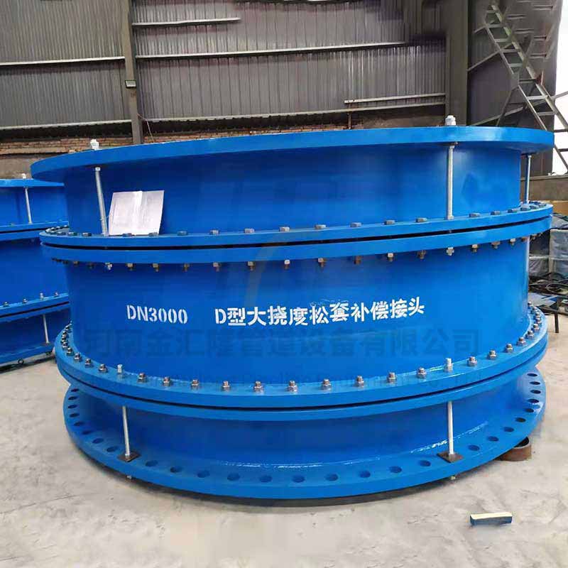
| 3000 | 3020 | 3315 | 3220 | 68-Φ48 | 3405 | 3290 | 68-Φ60 | |||
| 3200 | 3220 | 3525 | 3430 | 72-Φ48 | – | – | – | |||
| 3400 | 3420 | 3735 | 3640 | 76-Φ48 | – | – | – | |||
| 3600 | 3620 | 3970 | 3860 | 80-Φ56 | – | – | – | |||
PS:The above data is for reference only and applies to sizes from DN15 to DN4000. Please contact us immediately for more details!